Friday, December 18, 2015

The ultimate guide to virtualization swap files!

Most operating systems natively support RAM over-extension. This is accomplished by using a temporary file on the hard drive to store RAM blocks that are not currently being actively processed so that more RAM is available for blocks that do need current processing. This file is called a swapfile or a pagefile depending on the OS. This is never a good thing, because disk is always slower than Ram speed (don't believe me? click here) But it is sometimes a necessary thing.

Managing Swapfiles and Pagefiles can be confusing in VMware or Hyper-V because there are multiple files to configure at different levels.


  1. Guest VM's native OS swapfile
  2. Host related swapfile
  3. Hypervisor's per-guest VM swapfile


1) Guest VM's native OS swapfile

Even though you may assign 4 GB of RAM to a virtual machine, the OS running in that system may choose to create it's own pagefile on whatever virtual disks you provide according to its native behavior based on the full amount of "physical" RAM that it sees. The Hypervisor has no role in if or how a guest OS chooses to build or use a swapfile. This must be completely managed from within the Guest OS. However, remember that as a virtualization administrator you could certainly create a dedicated virtual hard drive file that is placed on a fast storage tier and then within the Guest OS ensure that this disk is used for paging. 


2) Host related swapfile

Just like the guest OS, your virtualization host has a swapfile or pagefile to support not having enough memory to perform its duties associated with being a virtualization infrastructure: (provisioning new VMs, vMotioning, etc) 

2a) VMWare System Swapfile using the Web Client: This is done via Hosts and Clusters -> Host -> Manage Tab -> Settings SubTab -> System Swap

vCenter Server Web Client configuring Host System Swap File
Edit System Swap Settings:

  • Enabled - if unchecked = ALL RAM ALL THE TIME - NO SWAPFILE!
  • The Datastore - Use a specific datastore
  • Host Cache - use part of the host cache.
  • Preferred swap file location - Use the host's preferred swap file location 

2b) Windows Server with Hyper-V: this is managed via the system control panel -> Advanced Tab -> Performance -> Settings... -> Advanced Tab -> Virtual Memory -> Change... 3) VM related swap files.

Server 2012 R2 Hyper-V server configuring Host PageFile
  • If all page files are removed = ALL RAM ALL THE TIME - NO SWAPFILE!
  • Don't forget to click "SET" after configuring a pagefile on a disk, otherwise nothing happened.

Hyper-V Server or Windows Server Server Core Host Swapfile

Modification is done by script or command line entries:

Add a 2 Gb Pagefile:
wmic pagefileset create name="E:\pagefile.sys"
wmic pagefileset where name="E:\\pagefile.sys" set InitialSize=2048,MaximumSize=2048

Delete a pagefile:
wmic pagefileset where name="C:\\pagefile.sys" delete


3) Hypervisor's per-guest VM Swapfile 

Modern hypervisors create a temporary swap file for hypervisor related memory management needs. This is NOT a swapfile that the Guest OS could ever see or use for its own swapfile needs! However, you may want this to be placed on an efficient disk to ensure that VMs boot as efficiently as possible. There are some key differences in how ESXi and Hyper-V use these files.

VMWare:

The host creates VMX swap files automatically, provided there is sufficient free disk space at the time a virtual machine is powered on. If it cannot be created, it prevents power on! 

This file is used because while physical memory is reserved for the system at powered on, memory for needs like the virtual machine monitor (VMM) and virtual devices can be swapped after initialization. The VMX swap feature means that a the 50MB+ for live VMX memory needs can shrink to only 10MB, freeing up memory resources for other needs. This is critical in overcommitted memory situations. 

By default, the swap file is created in the same location as the virtual machine's configuration file, but you may change the swapfile datastore datastore to another shared storage location. Moving the swapfile to a local datastore may improve local performance, but it may also slow vMotions later because pages swapped to a local swap file on the source host must be transferred across the network to the destination host

Hyper-V:
Smart Paging in Hyper-V is used only when the following is true:

  • The VM is being restarted (directly or via a host restart)
  • The hypervisor discovers that there is no available RAM
  • No memory can currently be reclaimed any other VMs running on the host


At that time the Smart Paging file is used by the VM as memory to complete startup. Within 10 minutes, that memory mapped to the Smart Paging will need to be provisioned into RAM and the the Smart Paging file will be deleted.  The Smart Paging feature is ONLY to provide reliable restarts (not cold boot or running out of RAM later) of VMs

3a) How to configure the vSphere web client to configure VM support swapfile: Hosts & Clusters -> Host -> Manage Tab -> Settings SubTab -> Virtual Machines -> Swap File Location
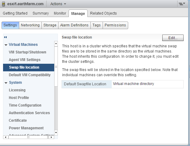
vSphere Web client configuring Default Swap File Location

vSphere Desktop Client to configure VM support swapfile: Select Host -> Configuration Tab -> Software Group - Virtual Machine Swapfile Location


This setting can also be overridden on a per-VM basis if needed in the VM Swapfile Location property

3b) Hyper-V SmartPage: Select a VM -> Right Click (Or Actions) - Settings -> Smart Paging File Location


The file location is determined during installation, then reconfigured on a VM by VM basis in their management related properties:


I hope that you feel a little more solid on the 3 types of swapfiles that you will run into when managing virtualization!

Keep it virtual!


Thursday, December 17, 2015

An easy to understand description of VLANs for Cisco, HP, VMWare, or Microsoft

VLANs can be confusing for virtualization administrators, because it takes a really solid understanding of networking to then be abstracted into a virtual environment, which can then be configured multiple ways.
Let's make sure we're on the same page with VLANs first

Let's think about a physical environment that is segmented without any VLANS
 
If we think about networks from a chronological perspective, we start with just the green local area network at the top. All your local clients were in a local broadcast domain with a single network ID. And the living was easy.
Then LANs continued to grow and grow, which caused too many broadcasts, traffic congestion, and security vulnerabilities... all because all the devices were playing in the same "sandbox."
 
So to divide the LAN we ran a dedicated cable from a newly dedicated interface on the router, installed a separate switch, and routed between the LANs, as seen in the diagram above.
 
Question: Why would anyone ever want anything better than that solution?
#1 - Money: High speed Ethernet interfaces on routers are a costly proposition, only superseded by purchasing entirely new routers to handle the traffic from each network. Additionally, every subnet needs a dedicated switch. What if a 48 port switch is serving a network of only 10 hosts? 37 wasted ports.
#2 - Management: To reassign a host to a different subnet means moving their patch cable to a physically different switch. This is a manual, physical process that requires going into the racks and mucking about - always an additional risk, easy to make mistakes

The good news is that soon one of the first network virtualization technologies came into being. Instead of having to buy additional switches and router interfaces, we can use virtual LANs (VLANs)

- VLANs allow us to virtualize networks using two key components:
1) Switch ports are virtualized so that instead of one switch you can have the effect of having two or three or more switches from a single physical switch, and then you can spread these multiple virtual switches across multiple physical switches!
2) Router interfaces are also virtualized, using sub-interfaces on physical routers or virtual VLAN interfaces on multilayer switches. Each virtualized router interface will be configured to "plug in" to the virtual switch. This means that one uplink could support a connection to 20 different subnets!

So how do you go about virtualization? It's all about playing a game of tag. Each switch's access port (a port going to an end station such as a server, desktop, phone, or router) will be tagged with a particular VLAN number, determined arbitrarily by the administrator.  (Side note, many administrators make their lives easier by creating a loose association between VLANs and subnet IDs. For example, the 192.168.5.0 subnet could be assigned VLAN 5 for simplicity.)

So each VLAN is identified by a number and the default VLAN is VLAN 1. All ports are assigned to VLAN 1 by default, meaning that the switch functions like an unmanaged switch, all ports will forward, filter, and flood with all other ports. Since this is the case, by default, VLAN tagging (inserting the tag ID into the frame) is skipped by default for VLAN 1. This skipping can only be done for one VLAN ID number, and is known as the "native VLAN". 

But now we choose to subdivide the switch by adding VLAN 2.  Generally on a switch you will have the opportunity to provide a VLAN name, which makes it a more sensical device (ie: HR_192.168.5.0 for the Human Resources subnet using 192.168.5.0)

Now that we two different VLANs an administrator needs to assign access ports to that VLAN.

This effectively turns a switch from this:
(Switch with all ports still on VLAN 1)


into this:


Remember, the devices connected to the switch know nothing about VLANs. But now the switch has virtualized two networks instead of one, which means that traffic must be ROUTED from one VLAN into the other, not just switch. 

In order to allow multiple switches and routers to participate in these VLANs we must modify the standard Ethernet frame and insert a VLAN tag number so that all devices can respect the defined VLAN boundaries. Tagging is done between devices over what are known as trunk ports. Trunk ports are used when connecting switches to each other or when connecting switches with multiple vlans to a router. Trunk ports are not assigned a VLAN number because their job is to carry ALL VLAN traffic upstream to a router and to take the returning packets and forward them to the correct access ports. VLAN ID numbers are stripped from the frames before they enter an access port.

That allows for this:


With this configuration you can see that we have the equivalent of 4 switches instead of two, with two switches in each broadcast domain. The great thing about the configuration above is that a device in VLAN 1 can switch to another device in VLAN 1 (or a VLAN 2 device to another VLAN 2 device) at high speeds. However, if a device wants to connect to another device across VLANs (VLAN 1 PC to a VLAN 2 Server, for example) then they had better know the know the IP address of the sub-interface (virtual interface) of their L3 routing service! In other words, they must route as if they were physically connected to different physical interfaces of the router.


But the real beauty of all this is that any device could be moved to a different subnet by reconfiguring the VLAN ID of an access port to a different number. As long as all the switches have the same VLAN ID numbers (and the router has VLAN associated sub-interfaces.

A little more about the native VLAN. The default VLAN is VLAN 1 (what all ports start off as). The default VLAN is also the native VLAN (untagged "assumed" VLAN number) by default. This was useful when connecting unmanaged and managed switches and in carrying management traffic back in the day. However, for security reasons, it is usually a best practice to change the native vlan to a different, unused VLAN ID number (such as 999). This ensures that are no assumptions, and therefore no annoying security holes. Now VLAN1 frames will be tagged as VLAN 1 just like all the other VLANs

When VLAN 2 is added, the VLAN tag is added to frames that are a part of VLAN 2. We now have two VLANs, and at least one of them must be tagged to be identified. 

Now, let’s add VLAN 3.  In this setup, two VLANs would need to be tagged, one would not because it was the original lan (VLAN)  The VLAN that is not tagged is known as the native VLAN.


There are a lot of questions of when and why to use the native VLAN or if you should use the native VLAN at all.  As always in IT, the answer is, it depends on what you are doing. VLAN 1 does not have to be your management VLAN.  It does not have to be the native or untagged VLAN. You can do whatever you need for your environment.  Typically, I do not use the native VLAN for security reasons, and I choose to tag everything. 

Remember that all of this is true whether you are dealing with a physical switch or a hypervisor driven virtual switch on Microsoft Hyper-V or VMWare ESXi. Trunk ports between switches, defined VLANs omnipresent, Access ports with VLAN ID numbers on individual access ports.

Keep it clean, keep it safe.

Monday, December 14, 2015

Get Trunk!!!

Remember - you can't carry traffic for multiple VLANs unless you...


Smiles,


Monday, November 30, 2015

How to control wireless vs wired priority in Windows

A Student asked recently how to control wireless vs. LAN priorities in Windows 7. Wireless was being used, even when on the LAN. One absolute way to do this is by disabling the Wireless when connected to the LAN – but this requires vendor support – like in some Dell BIOS’ there’s an option to do this. But a simpler method may be to override the default interface metric used by IP on the wired or wireless interface. Here's the what and why and how: 

If I go to the route print command on a system with wired and wireless I see the following :


I’ve highlighted the two interface IPs which show their bizarre local on-link metrics for local communications. (FWI, these are all derived from what we will be configuring directly)  What really matters here is the metric to the default gateway routes circled at the top – which one will be used?

In my case 192.168.2.9 will be used with the metric of 20. How did it get that metric of 20? It’s certainly not 20 hops to the default gateway! Well a metric does not mean hop count. A metric is the just the relative measure to determine preference among routing methodologies.
Well, as we would learn from http://support.microsoft.com/kb/299540 the metric for each interface to the default gateway is based upon a link speed range:

Link Speed Metrics for Operating Systems after XP sp2
10 = > 200 Mb 
20 = Between 80 Mb and 200 Mb 
25 = Between 20 Mb, and 80 Mb 
30 = Between 4 Mb, and 20 Mb 
40 = Between 500 Kb and 4 Mb 
50 = < 500 Kb 
So in my scenario it’s because it has the Link speed of 100mb/s which gives it an automatic metric of 20, which is better than the 192.168.2.7 which has a link speed of 72mb/s (wireless) which earns it an automatic metric of 25. So in my scenario, the LAN is preferred over the Wireless, and all is well.

The real problem shows up with a 802.11n interface that gets about 150mb/s and a LAN interface with 100mb/s. Then they both get a metric of 20, and it’s a toss up which one gets used, and you may find that it's the wireless!

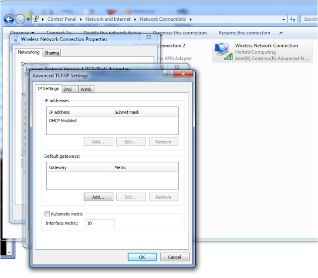
This is the situation when you will override the automatic metric by going to the advanced interface property dialog box of the TCP/IP settings to lower the metric of the preferred NIC (or raise the metric of the the less preferred NIC)

In my scenario, I'm lowering the metric of my Wireless to force it to be the preferred Interface.  After making this change, we can see that the default gateway is now preferred to go through this interface that his this metric.
I’m going to undo this now so that my LAN is the preferred interface again!

Hopefully this deepens your understanding of how Microsoft is managing your multihomed system when it comes to routing. And these are really routing rules that apply to all routing devices and protocols as well, so this knowledge can serve you when administering any routing device and managing two routes to the same network based on the same protocol with differing metrics.

Good luck getting Windows to behave itself!

Monday, November 23, 2015

Building a SharePoint, SQL and Exchange Lab: Logfiles Tip

I work with a lot of lab or development scenarios. These situations are usually a fast buildup and a quick teardown with little connective tissue or infrastructure.However some of these environments may last a while, and when they do, they can start to trigger "DISK SPRAWL" (que dramatic music)

Here's the deal, both Microsoft Exchange and Microsoft SQL Server have log files that are used to ensure the integrity of their databases in case of disk failure or power outage. As a safety check, these logs are not cleared until they have been backed up. So backup of these log files enables them to be overwritten. Conversely, however, NOT performing log file backups on these servers (say in a lab or development environment) means that they grow... and grow... and grow... sometimes to terabytes in size!

Two solutions:
1) Perform backups as if you were in a production environment

2) Disable the safety check so that your lab/dev/test environment doesn't preserve the log files past the point in which data from memory is written to disk.

Here's how to do the latter for both Exchange and SQL

Exchange: Enable Circular Log Files on the Exchange Mailbox Database


1) Open Internet Explorer and Browse to the Exchange 2013 ECP URL (usually http://servername/ecp/
2) Log in with an administrative account.


3) Select "Servers" from the Lefthand Navigation bar
4) Select "Databases" from the Contextual Horizontal Navigation Bar
5) Select the database you want to enable Circular logging for and click the “Edit” pencil


6) Click on "Maintenance "
7) Click on "Enable circular logging"
8) Click on "save "
 

9) Click OK to the warning message that appears


10) Select the database and click the elipses (...) in the menu bar and choose "Dismount"


11) Click on "Yes"

12) Select the database and click the elipses (...) in the menu bar and choose Mount"
13) Click on "Yes"

And now you've enabled circular logging in Exchange.  That was the easy one.

SQL: Enabling Simple Recovery Mode in your databases

For more information on SQL's Transaction Log and the Simple Recovery mode check out these other articles:
Preventing Transaction Log Fires
My SQL Transaction Log is huge - should I switch to simple recovery mode?

1) Open the SQL Server Management Studio
 
 
2) Log into your SQL instance with sysadmin credentials
 
 
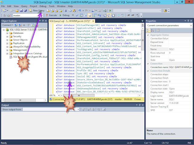
3) In the toolbar click "New Query"
 

4) You could now either open up the properties of the master database and each user database, go to the options section, and choose "simple" from the drop down menu for Recovery Mode or...

Copy and Paste the following script into the SQL Server Management Window

Use Master
alter database [model] set recovery simpleselect 'alter database ['+name+'] set recovery simple' from master.sys.databases where database_id > 4 and state_desc = 'online' 
select 'use ['+name+'] checkpoint' from master.sys.databases where database_id > 4 and state_desc = 'online'
select 'DBCC Shrinkdatabase (['+name+'], 0) ' from master.sys.databases where database_id > 4 and state_desc = 'online'
select 'DBCC Shrinkdatabase (['+name+'], 0, TRUNCATEONLY) ' from master.sys.databases where database_id > 4 and state_desc = 'online'


5) Click Execute -

NOTE: If you perform these actions BEFORE installing SharePoint then you are done!
Already installed SharePoint? Keep going! -

6) Right Click in the first results area below the script code and select "Select All"
7) Right Click in the first results area below the script code and select "Copy"


8) Click New Query
9) Paste the selected text into the query script window


10) Click Execute
11) Verify the commands completed successfully


12) Click the script file select drop down
13) Choose the first script file

14) Scroll down to the Second result block
15) Repeat steps 6-13 for the Second result block


16) Scroll down to the Third result block
17) Repeat steps 6-13 for the Third result block

18) Scroll down to the Fourth result block
19) Repeat steps 6-11 for the Fourth result block

You're done - your log files are now under control for your lab/test/dev environment!


Thursday, November 5, 2015

vCenter and VCSA database choices and Host and VM support in vCenter 6.0

It can get confusing trying to track down how many hosts and VMs can be hosted with a vCenter Server or vCenter Server Appliance based upon the choice of database model that I want to work with.

vCenter Server


embedded 5.5 vCenter - vPostgres (prior versions used SQL Express) - 5 Hosts and 50 VMs
embedded 6.0 vCenter - vPostgres - 20 Hosts and 200 VMs
external vCenter- Microsoft SQL - 1,000 Hosts and 10,000 VMs

vCenter Server Appliance


embedded 5.5 vCSA - vPostgres - 100 Hosts and 3,000 VMs
embedded 6.0 vCSA - vPostgres  - 1,000 Hosts and 10,000 VMs
external vCenter - ORACLE - 1,000 Hosts and 10,000 VMs (primarily for bringing in an existing database with content)

So... the vCSA now allows full size support and now supports Linked Mode, plus you avoid paying Windows License or MS SQL Licenses and the whole Windows Security attack vector.

If you are using the VCS and you would like to move to the VCSA you have two options:
Rebuild intelligently - really your best option
Use this fling: https://labs.vmware.com/flings/vcs-to-vcva-converter

So get to the VCSA - it's awesome!

Monday, November 2, 2015

Can I install windows 10 with a local account? YES!

I get asked this more often than Microsoft would like. Yes, it's great to have a system set up with a built-in cloud presence. But some systems just don't have Internet access or relate to a live body with an email address. And some people just don't want that much Microsoft, even when they are buying their OS.

So here's the trick to installing a local account on Windows 10 box during installation. Pretend to go along with the plan then chicken out at the last second.
Step 1

Step 2

Step 3
And you've installed with a local account! The process is similar when you go to create an account after installation - keep going and look for an option duck out and get your circa 1995 local user account groove on.

Hope it helps!

Thursday, October 29, 2015

Majorbacon's 6 steps guide to easy IPv4 Subnetting

Subnetting is a process that you just have to practice. Here's what I do so that I can quickly work through subnetting test questions (or real life situations... there's a reason these are on tests you know)

THE PROCESS:

  1. Read the question.  Know what network ID you are starting with and what your GOAL is: Do you need to obtain a certain number of subnets out of your original network or do you need to ensure a certain number of hosts are available in each subnet?
  2. Write your binary table on your paper.  If you can multiply by two, you can do this
  3.  Use one of two magic formulas to determine the number of bits that will be used in the new subnet mask
    • 2n  >= your desired number of subnets, where n is the number of new ones in the new subnet mask.  The rest of the subnet mask will be composed of binary zeros.
    • 2h-2 >= your desired number of hosts, where h is the number of zeros left in the new subnet mask.  The rest of the subnet mask will be composed of binary ones.

  4. Based on this, write out your new subnet mask (in binary, counting ones or zeros as necessary).
  5. In order to figure out the number of hosts you have in each subnet, use 2h-2, where h is the number of zeros in your subnet mask. 
  6. In order to figure out the total number of subnets you have, use 2n, where n is the number of new ones (not total ones) in your subnet mask.
  7. In order to determine your subnet IDs we need to find the block value. Start with your original network ID for the first subnet, but remember it has a new subnet mask. Your next subnet will be one block value away.  How much is your block value?  It’s determined by the “least significant bit”, the last one in the subnet mask.  Look up the column value for this bit in the table because this bit will be the increment from one network to the next, in that same octet!  
    • Or Skip the table and use this trick: 256 minus the last positive octet will also yield the block value of the networks

WORK THE EXAMPLE:


1.    You have a Class C network, 202.5.4.0 that you want to subnet into 6 subnets.
2.    We write down the all-important table:


3.    2n  >= your Goal, therefore 23 = 8 >= 6 desired subnets.


4.    A Class C subnet mask is 255.255.255.0, so if we add 3 ones, it will be 255.255.255.11100000 or 255.255.255.224 - that's 27 binary ones in the subnet mask, so our CIDR notation will be /27. (If you remember that a class C address starts as a CIDR /24 then you could just do /24+3 bits = /27)

5.    We have five zeros in the subnet mask, so 25-2=30 hosts per subnet, and we have added 3 ones to the subnet mask, so 23=8 new subnets


6.    Our increment is based on the least significant bit in the subnet mask, which in binary was 255.255.255.11100000.  If we examine the last octet compared to our table we see that the last one is in the thirty-two column.  (Also, 256-224=32)


That was 6 steps - so we should be done! Let's review:
  • So, our network started as 202.5.4.0/24 (the /24 being CIDR notation for a 24-bit 255.255.255.0 subnet mask). 
  • Now we have a new subnet mask 255.255.255.224, CIDR notation /27
  • Our first subnet ID is the same as the original network ID but with a new subnet mask: 205.5.4.0/27
  • We determined our block value is by 32 in the fourth octet
    • Therefore our second subnet would be: 202.5.4.32/27, 
    • Third: 202.5.4.64/27
    • Fourth: 202.5.4.92/27
    • Fifth: 202.5.4.128/27
    • Sixth: 202.5.4.160/27
    • Seventh: 202.5.4.192/27
    • and finally Eighth: 202.5.4.224/27
  • So there are the 8 subnets that each have 30 hosts per subnet, as expected!

Please note that if you count all of those subnets up, you have 8 of them.  The amount we predicted back in step 3. Great job!

More subnetting examples and practice to come:
Keep practicing - here are some random subnetting question generators:
http://david.clauss.us/Subneting/
http://www.subnettingquestions.com/

Have fun!